Feeds:
Posts
Comments

U.S. Water is pleased to announce the launch of our new website at http://www.uswaterservices.com. Our goal with the launch of the new site was to provide an integrated approach to water management – providing customers with an easy to use functionality that can help them address their issues and meet their goals in a cost-effective and complete manner. 

With the launch of our new website, we have also moved our blog for greater accessibility. Any subscribers are welcome to re-subscribe to our new blog located at http://www.uswaterservices.com/news which will allow you to receive notification when new blog posts and industry information have been posted.

Subscribe to U.S. Water’s Blog

As always, if you have any questions, please feel free to contact us directly at info@uswaterservices.com.

When treating Thermal Energy Systems or Large Chilled Water systems the following standards should be followed to minimize costs to chemically treat these systems and protect the equipment assets.

Filtration

Use of Biocides

Use of Corrosion Inhibitors

General Maintenance and Monitoring 

Filtration – Given the size of these systems the most effective filtration is low micron sand filtration.  Since draining or flushing the system to reduce suspended solids is normally not an option, filtration is required as part of the program.  In the case of TES systems, filtration is required.  It is recommended that the filtration be able to remove down to 0.35 micron particles.  The filtration sizing should be based on the volume of the system as well as turnover rate (the time it takes for the volume of the system to pass through the filter).  It is recommended that the system turnover rate not exceed (5) days. Annually, each filter should be tested for biological activity (sand or multimedia filter only) and suspended solids removal performance.   Filter performance can be tested using a particle study analysis of both the incoming and exiting water sources of the filter while in operation.  This analysis is relatively inexpensive and can determine the percent removal rate at different micron sizes. This can be compared to the design capabilities of the filter unit.  If the filter is not operating at design capabilities, inspection and maintenance of the filter should be completed. 

In some cases facilities do not use their thermally stratified thermal storage systems in the winter.  If this is the case, considerations on the location of the filter or an added filter may be required.  This will also impact the location of where chemical is added and testing. 

Biocides are required to maintain the biological counts in the system within a range that minimizes fouling, microbio influenced corrosion and suspended solids.  It is recommended that bulk water microbio testing be done as a minimum quarterly and on the following species and maintain the following control ranges: 

Total Aerobic Bacteria  …………………………..………< 1000 cfu

SRB (Sulfate Reducing Bacteria) ………………………………ND

IRB (Iron Reducing Bacteria) ………………………………….ND

Denitrifying Bacteria …………………………………………….ND

Nitrifying Bacteria ………………………………………………….ND

ND – Non Detectable – Barts Testing Methodology

If the levels exceed these control ranges, then a biocide should be used to bring the levels back into range.  Each time a biocide is added, the system should be retested (14) days after application.  

It is not uncommon that the bulk water bacteria levels show good results and yet there is considerable surface biological activity still present, mostly in biofilm.  When testing systems, considerations should be given to doing pipe swab testing the same species.  We expect the levels on the pipe surface to be higher than that of the bulk water but should not be more than 5 times the level in the bulk water.   In the case of anaerobic bacteria, the levels should be < 50 cfu.   If this is the case, then a biocide should be used to bring the levels back into range and retested in (14) days. 

There are a number of biocides available to manage biological activity.  The following biocides have been very effective on a shock basis in the past at the prescribed dosages; 

120 PPM of 50% Gluteraldhyde

240 PPM of a 1.5% Copper Free Isothiazoline

1.0  PPM free residual of Chlorine Dioxide

 Depending the biological levels, the most aggressive and in some cases the most cost effective method to treat the system is with the use of Chlorine Dioxide.  This is a low residual oxidizing biocide that demonstrates very good biofilm removal and rapid destruction of biological activity in the systems.  The use of chlorine alone is NOT recommended as the system will see increased corrosion at the elevated chorine levels required in high pH water conditions.  Stabilized bromine products are also not recommended as the product can over stabilize over time with multiple applications reducing the effectiveness of the program. 

It is recommended that (2) proactive biocide applications be completed each year.  The type of biocide depends on the biological activity and the effectiveness of the biocide after each application.  If the system continues to have high biological activity after repeated biocide applications, then Chlorine Dioxide should be used. 

Corrosion Inhibitors play an important role to minimize corrosion and iron deposition on heat transfer surfaces.  There are a number of corrosion inhibitors that have been effective and are listed in order of effectiveness.  The cost of the program approach is also listed from highest to lowest price.

Molybdenum/Azole                     

Molybdenum/Silica/Azole

Silica/Azole

Boron/Azole

Note: The use of Molybdenum could exceed local municipality discharge limits.

It should be noted that the use of Nitrite, Phosphate or Phosphonate Corrosion Inhibitors should NOT be used as part of the program.  These programs can be food sources for bacteria. 

The program selected should be fed at a rate to provide < 0.5 MPY steel and < 0.1 MPY copper corrosion rates as measured with non passivated corrosion coupons.

Water Chemistry should be maintained and tested on a regular basis to monitor and maintain the proper performance standards.

Thermal Energy System – Large Chilled Water System Chemical Performance Standards

Water Quality Parameter

Level

Units of Measure

pH

8.5-9.5

Standard Units

Conductivity

<3000

Umhos/cm

Turbidity

<20

NTU

Iron

<1.0

mg/L

Copper

<0.5

mg/L

Total Aerobic Bacteria

<1000

CFU/ml

Total Anaerobic Bacteria

ND – Not Detectable

CFU/ml

Chemical Oxygen Demand

<100

mg/L

Chemical Treatment

Free Azole

5-10

mg/L as Azole

Treatment – Molybate

100-120

mg/L as MO

Treatment – Moly/Silica

50-70 ppm MO / 50-70 ppm Sillica

mg/L as MO and SIO2

Treatment – Silicate

50-70 ppm Above Make-Up Water

mg/L as SIO2

Treatment – Azole (TT or B2T)

5-15

mg/mL

pH control plays an important role when controlling mild steel corrosion.  Maintaining the pH above 8.5 helps minimize mild steel corrosion. It is not uncommon to see pH reduction in these systems.  This is usually a result of high levels of microbio activity both in the bulk water and biofilm.  If you see the pH drop, biological testing of both bulk water and pipe surface should be done. 

General Maintenance and monitoring should be done on a regular basis.  The following actions should be considered when maintaining the water chemistry of these systems:

Water Meter should be installed on the makeup line to the system.  Monitoring water usage will allow the facility to respond to any leaks.  The water loss from these systems should be <1 % of the system volume per year. Any water loss above this should be identified and repaired.

Corrosion Monitoring of Steel and Copper as well as any other metallurgy that might be in the system should be done quarterly.  The corrosion rates should be very low in properly treated systems.  The corrosion coupon rack is also an excellent sample point for biological swab sampling of the system.

TES tanks should be inspected annually.  This can be done via underwater cameras or through sampling the tanks at different levels off the bottom.  Since TES tanks are the low point of the system, any suspended solids will settle at the bottom of the tank.  This can lead to biological influenced corrosion of the tank and a source of biological contamination for the entire system.  If the sludge level is significant, then the tank should be cleaned.  There are a number of companies that can clean tanks without draining the system.

Spring Start-Up
Many facilities isolate, drain and winterize air handler coils for the winter months.  In most cases glycol is used to winterize coils.   Bringing these units back on line in the spring creates an influx of suspended solids, iron corrosion products and residual glycol which at low levels is a food source for bacteria.  It can take months to get the system back into specification. 

In order to reduce these issues, the following measures should be considered;

  1. Use air to remove the water from coils instead of glycol
  2. Prior to isolating coils, make sure the biological activity both bulk water and surface levels are within range.  Consideration should be given to adding a maintenance dosage of biocide prior to winterizing
  3. Make sure your corrosion control program is in range.
  4. Prior to putting the air handlers back on line, flush the units with clean water.

Once the air handlers are back on line, rebalance the water chemistry and make sure the filter units are working properly. 

by John Vogt, U.S. Water Strategic Business Leader for the Power Industry

With more and more steam boilers being asked to provide intermittent service, there is renewed focus on the proper treatment of boiler systems while they are off line. In the Power Industry it is not uncommon for a combined cycle plant to operate less than 30% of the time, meaning the vast majority of the time the boiler is idle. The rise of renewable power assets that have intermittent and sometimes unpredictable availability (wind, and solar) coupled with variable demand for electricity makes plant “cycling” between operation and standby a business necessity. While plant cycling was formerly reserved primarily for natural gas plants, more and more coal plants are being asked to run intermittently as well. To further complicate things, most power purchase agreements are written such that the power plant must be at “full
load” in a matter of hours, so additional attention must be given to ensure that this can be time hurdle can be met. Since most boiler makeup systems do not have the capacity to fill the boiler system quickly enough, most cycling plants must idle while the boiler is full of water. This presents some technical challenges as plant asset protection can conflict with business realities that often results in some compromises. This article will explore some of the options that are available to the boiler operator and weigh the risk factors associated with each.

Concerns 
Having removed heat from the system and lowered the scaling tendency of the boiler cycle waters, the primary concern with off-line boilers is metal loss, or corrosion. This can occur in several ways. The first and most predominant is dissolved oxygen corrosion. As the water temperature decreases, the dissolved oxygen content in that water will increase provided the water is exposed to oxygen or ambient air. Once oxygenated water contacts mild steel, corrosion will initiate. The other common corrosion mechanism is acidic corrosion caused by stratification or concentration cells that develop due to stagnant conditions. Corrosion of the boiler internal surfaces not only weakens the integrity of the system, but also releases iron oxides into the boiler water. While not a concern when the boiler system is off line, iron scaling can be a concern after start-up as these iron oxides produced during layup (corrosion products) can deposit on steam generating tubes.

Layup Methods
Dry Layup
The preferred choice for boiler layup is dry layup. Removing the water from the system is the best way to prevent off-line corrosion. This accomplished by draining the water from the boiler while it is still hot and under 25 – 50 psi of system pressure. This is done so that the residual heat can dry the internal surfaces and ensure that all “dead legs” are drained. In geographic areas that commonly have relative humidity readings of >30%, a desiccant may be used to prevent dew from collecting inside the boiler, or dehumidified air can be circulated throughout the waterside and fireside areas of the boiler. If a desiccant is used, care must be taken so that the desiccant can be completely removed prior to start-up. The general rule of thumb for silica based desiccants are 10 pounds of silica gel per 1000 gallons of boiler capacity. Even if the waterside layup choice is wet layup, dry layup is needed for the fireside surfaces. Unlike the relatively clean waterside areas, a boiler’s fireside can contain deposits of sulfur or other fuel containing contaminants that, when wet, can be very corrosive. Once the water is removed from the system, the primary concern is to keep the boiler surface temperatures above the ambient dew point. One scenario that can develop involves cool tube surfaces and the influx of warm air that can be a result of rapidly changing ambient environments in the spring or fall. In this case, condensation can occur on the cool boiler surfaces and provide the moisture needed to initiate corrosion. So removing the boiler water/moisture and preventing new sources of moisture are essential to a good dry boiler layup. Most times this requires some level of isolation from ambient air, so stack dampers or balloons are employed to minimize the influx of rain and humid air on the fireside. In practice, dry layup while the most resistant to off-line damage is rarely employed on the waterside of the boiler because it delays the start up of the plant.

Wet Layup
The goals of wet layup are to prevent oxygen and acidic corrosion and have the boiler internal chemistry ready to operate the boiler within operating control limits when the boiler is called upon for service. To prevent acidic corrosion, the internal pH should be elevated to between 10.0 and 11.0 prior to shut down so that the water is well mixed. Once off-line, the boiler water should be re-circulated to prevent pH stratification and acidic concentration cells from developing. pH elevation should be accomplished with a suitable chemical that is compatible with your cycle chemistry and metallurgy. 

To prevent oxygen ingress, there are two basic methods; hot layup and cold layup. Hot layup is preferred if practical because it reduces the thermal stresses on the system metallurgy but, of course, requires a source of heat. The idea is to keep the system under positive pressure so that oxygen cannot enter the boiler. If the boiler is only planning on being out of service for several hours, the residual system heat may be sufficient to keep the system under pressure. If an extended layup is anticipated, other methods must be considered. 

If there is an adjacent boiler that is operating or an auxiliary boiler, the blowdown from that boiler can be sent to the off-line boiler, termed cascading blowdown. Depending upon the amount of blowdown, this may be enough heat to do the job. The optimum entry point to the boiler in layup is in the lower header or mud drum so that natural circulation can be achieved. The primary concerns with cascading blowdown involve dealing with the pressure differential between two boilers and controlling the water levels in the off-line boiler. Also, if the operating boiler is much smaller than the off-line boiler (or has too little blowdown), cascading blowdown may not provide enough heat to maintain a positive pressure on the system.

Another method is to install a heating coil in the lower header (or mud drum). Either steam or electric coils can be used here. This is a very effective method of hot layup and alleviates some of the concerns with cascading blowdowns. If enough heat can be supplied to the boiler, positive pressure and natural circulation can be achieved. 

One last method of hot layup that has been used is the injection of steam (called steam sparging) into the off-line boiler. While this may be simpler than installing a heating coil, there are several disadvantages of direct steam sparging. First, the injected steam will condense and add liquid to the boiler so the boiler water levels must me managed (as with cascading blowdown). Second, the steam will dilute the boiler chemistry so chemistry monitoring and chemical additions will be needed in order to maintain the system pH. Finally, direct steam injection can cause some damage from steam impingement if care is not taken to the selection of the location of the injection point.

If there is not a ready heat source for hot (wet) layup, the injection of inert nitrogen gas can be utilized to keep a positive pressure on the boiler. As with hot layup, the system pH should be elevated (10.0 – 11.0). A source of nitrogen (purchased tanks or an on-site nitrogen generator) is required and only about 5 psi of pressure is needed, controlled by a pressure regulator. Usually the regulator is set to inject the nitrogen at 3 psi and stop at 5 psi. If the regulator is set above 5 psi, the nitrogen requirement will be much higher as experience has shown that the nitrogen will find a way out of the system. The main disadvantage of cold layup is that natural circulation cannot be achieved. It is recommended that a small, low pressure circulating pump be installed to provide the needed circulation. This pump must be isolated prior to start-up as is will most likely not be designed for the normal system operating pressures.

The final widely used (and not recommended) method of cold (wet) layup is to allow the system to drop to ambient pressure and attempt to chemically scavenge the dissolved oxygen from the boiler water. While better than doing nothing, the levels of oxygen scavenger required to chemically scavenge ambient water is very high and at the lower temperatures, the reaction is very slow. In addition, most chemical oxygen scavengers are acidic, so additional pH adjustments are usually required. Finally, EPRI research has shown that reducing conditions can increase the solubility of the protective magnetite layer which could lead to unprotected internal surfaces.


Every year the cooling system for an industrial plant providing comfort cooling was shut down and drained for the winter months. Historically, during this shut down period the cooling water piping and equipment would experience severe corrosion. During start-up of the cooling system the next spring, iron flakes would peel off the piping plugging strainers and heat transfer equipment. This would interfere with the efficiency of the production process and cause an increase in maintenance. 

U.S. Water Services recommended Cooling Tower Toads to solve this difficult problem. Cooling Tower Toads would provide a Vapor Corrosion Inhibitor (VCI) protective layer that would film all the metal components not allowing oxygen and water to create corrosion cells on the surface of the metal. In addition, the VCI would coat recessed and inaccessible areas such as the vapor spaces of piping providing protection to these hard to reach areas. With the ability of the VCI to replenish coatings that are disturbed or depleted, the protection would last for the entire layup season.

One box of 2.2 pound bags of Cooling Tower Toad added to the tower basin for every 1,000 gallons of water. The cooling tower basins were drained to the lowest possible operating level to reduce the amount of water that needed to be treated. A non-ionic biocide was added to sterilize the system as a routine maintenance practice prior to shut down. 

The Cooling Tower Toads were removed from their outer bags and directly added to the tower basin. The inner poly-alcohol bag dissolved in approximately 5 minutes. The system was recirculated for 8 hours and then drained.

Inspection of the cooling system piping and heat transfer equipment showed a very noticeable improvement in the inhibition of rusting and corrosion thus reducing maintenance and increasing efficiency.

Consult your U.S. Water Services representative for Cooling Tower Layup Guidelines, as well as to see how the Cooling Tower Toads can help you minimize corrosion in your system by contacting us at 1-866-663-7633 or info@uswaterservices.com.


U.S. Water Services is always looking for new tools to make your facility’s boiler system more efficient. One of the tools is a U.S. Water Services boiler inspection. What is a boiler inspection you may ask? It is a thorough checkup of your internal and external boiler components in addition to the mandated inspections.

Boilers can be dangerous if not inspected and maintained properly. Each year, countless accidents, breakdowns and unnecessary shutdowns occur among industrial boilers. While boiler safety devices are designed to prevent dangerous conditions elevating into disasters, only proper boiler maintenance prevents the development of dangerous operating conditions in the first place by finding deficiencies before they become a serious problem. In addition to loss of life, boiler accidents can cause major structural damage to plants, facilities and equipment resulting in thousands to hundreds of thousands of dollars in repair and replacement losses.

Proper boiler maintenance, servicing and inspection is not only a safety issue, but also an economic matter. Regular boiler maintenance and inspections can provide system optimization. Boilers are high energy users; inefficient operation means wasted energy and increased operating costs. A boiler accounts for a large amount of the plant’s energy budget, and even a small decrease in a boiler’s efficiency can cause a sharp increase in energy costs. Proper water treatment is a key ingredient to making sure your boiler is operating properly. Raw water impurities that occur naturally in the feedwater may cause corrosion or sediment buildup, both of which reduce efficiency. Impurities lead to wasted energy because they necessitate routine blowdowns. The cleaner the water supply going into the unit, the fewer blowdowns you’ll need. U.S. Water has a complete line of boiler water chemicals designed to keep the water clean and your boiler operating at optimum efficiency.

Regular maintenance and inspection can also help extend the life of the vessel. Boiler downtime may force a manufacturing plant to shutdown operation and production, resulting in loss of income that can add up every hour the boiler is down. No plant owner wants emergency shutdowns or equipment downtime because boilers, or other equipment, weren’t serviced or inspected regularly.

U.S. Water Services Senior Regional Manager Steve Tapper has performed various boiler inspections throughout his tenure in the water treatment industry. “There are two important reasons to have U.S. Water Services inspect your company’s boilers,” Steve said. “First, when inspected by the state, the inspector is only looking to ensure the boiler meets state safety regulations. Second, because these systems shut down once or twice a year, this is the only time we can inspect the inside of the boiler to determine its efficiency and whether any modifications need to be made.”

It is important to remember that most problems don’t occur suddenly. They develop slowly overtime. So slowly sometimes, that they can be overlooked as the maintenance staff grow accustomed to the change without realizing it has taken place.  Maintaining a boiler is much like maintaining a car; you need to do it regularly to optimize efficiency and performance so that it doesn’t break down at an inopportune time. Boiler maintenance logs are probably one of the single best methods for keeping track of boiler maintenance. Boiler logs provide a continuous record of the boiler’s operation, maintenance and testing helping identify and detect changes that may have gone unnoticed.

Contact a U.S. Water Services Representative to find out more about how our Boiler Inspections can help you with prevent issues before they become problems. All of our boiler inspections follow these guidelines:

  • Personal Safety Equipment based on your procedures and ours.
  • Proper “Lockout” Procedure for boiler.
  • Inspect the steam drum from the generating tubes to the chemical feed line.
  • Inspect the bottom drum from the drum surfaces to the blowdown angle iron.
  • Inspect the fireside of boiler including but not limited to the furnace wall tubes, convection sections, superheater and refractory searching for deposits, blisters, alignment, and supports.
  • Check the headers, if present for deposits.
  • Inspect the deaerator including the storage section, sprays and trays.
  • Inspect other equipment such as the turbines, pumps and pretreatment equipment.
  • Document the results in an easy to read detailed report.
  • Set up meetings to discuss the boiler inspection’s results with you, the customer.

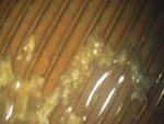
Visual inspection of chiller and evaporator tubes is a great tool to determine the effectiveness of a water treatment program. Effective use of a borescope can visually determine if a water treatment program is preventing scale formation, copper corrosion and biological fouling. Used in conjunction with an Eddy Current study, any tube defects can normally be seen visually with the use of a borescope. Pictures and videos can also document the conditions of the tubes.

When Should You Borescope Your Condensers and Evaporators?

Image

New condenser tube with a lateral tube defect.

U.S. Water Services recommends all new condenser or evaporator tubes be Eddy Current and borescoped to establish an initial point of reference. Figure 1 shows a tube defect in a new chiller before it went into operation. Early detection allows for tubes to be replaced prior to starting the equipment preventing potential early tube failures.


Image
Condenser tube showing biological fouling and deposits


After the initial inspection, scoping should be done yearly on condenser tubes and every two years on evaporator tubes to track the progress of the effectiveness of the water treatment program. This allows documentation of the tube conditions. Figure 4 shows early signs of biological fouling and deposition on the hot side of the tubes that would normally have been missed during inspection without the use of a borescope.

What Is The Difference Between A Borescope Study And An Eddy Current?

Eddy Current studies determine if there is any metal loss due to corrosion or defects. Eddy Current studies do not provide a visual picture of the tube surfaces. The value of the borescope study is to observe the amount of scale formation and surface corrosion that could lead to future permanent tube damage.

Asset protection is a concept that is steadily gaining notoreity in today’s industry. Many plants are looking for ways to optimize their system to get the most they can from their capital equipment, while simultanesouly protecting their equipment and system from a variety of potentially damaging, and costly, variables including water quality, corrosion, and scale.

Looking for the next level of service, plants are in need of a solutions provider that has your best interest in mind with reliable products and programs you can trust. You need a solution that focuses on not only optimization of your water treatment system, but also preventative maintenance to ensure that your system continues running effectively and efficiently for the long term.

WATER QUALITY

Dissolved minerals may affect suitability of water for a range of industrial purposes. The most familiar of these is probably the presence of ions of calcium and magnesium which can form deposits in heating equipment. Hard water can be softened with the use of sodium zeolite water softeners, which substitute calcium and magnesium ions with sodium. This process is ideal when applied to commercial and industrial water softening.

You can optimize your softener with a U.S. Water Brine Elution Study. When a softener with fresh resin is in service, the sodium ions in the surface layer of the bed are immediately exchanged with calcium and magnesium. This will produce soft water with very little residual hardness. The resin bed will continue to exchange its sodium ions with calcium and magnesium ions until the hardness concentration increases rapidly. Referred to as the “breakthrough point”, it is the point at which regeneration is needed.

The following is a typical regeneration sequence:

1) Counterflow backwash and resin. Specified rates based on temperature and manufacturer’s data. Backwashing removes surface deposits and fines, classifies resin and conditions the resin bed for proper regeneration.

2) Regenerate. Brine regeneration consists of educting saturated brine from a brine tank or other source and diluting it to generally 8-10% by weight NaCl. The brine should move through the resin bed, first increasing concentration, the reaching a peak and decreasing until only dilution water is present.

3) Rinse. The fast rinse cycle compacts the resin bed as well as rinsing the final residual brine from it.

Poor regeneration practices are often the cause of problems in zeolite softener systems. An elution study is used to identify and correct softener problems. The study plots the concentration (specific gravity) of brine from a zeolite softener during regeneration along with recording cycle times. The information is then used to troubleshoot and evaluate the system.

CORROSION

[Excerpt from “Rust Isn’t Sleeping” from Chemical Processing magazine.] “Corrosion has plagued process plants since the chemical industry began. After all, many sites handle materials that are inherently corrosive to steel or can become so under conditions that might occur. Acids, bases and salts all can harm hardware and equipment, as, of course, can water. Corrosion causes product contamination, leaks, and equipment malfunctions, which, in turn, can lead to quality, environmental and safety issues. Some major accidents have stemmed from corrosion. Even if a site doesn’t suffer overt mishaps, corrosion shortens the service life of assets. NACE International, formerly the National Association of Corrosion Engineers, (www.nace.org) puts the annual cost of corrosion in the chemical and pharmaceutical manufacturing and petroleum refining at over $5 billion in the U.S. alone.”

“Sometimes, corrosion itself doesn’t create a hazard, but lack of knowledge on the subject matter may get plants into trouble,” as Dirk Willard relates in his Field Notes column “Solve the Real Problem.” He cites a situation in which an engineer decided to replace carbon-steel bolts on a vessel with type 316 stainless steel ones. He didn’t realize this would require de-rating the pressure limit of the vessel by about 15%. If no one else had realized it either, the plant might have put itself at risk. Raising staff skills is important, but so too is an effective corrosion-monitoring program. But reacting to the consequences of corrosion rather than addressing issues before they become problems directly conflicts with the quest of many operating companies to achieve predictive maintenance.” By Mark Rosenzweig, Editor in Chief at Chemical Processing Magazine.

Some techniques to assess corrosion, such as the use of coupons, have proven their effectivenes for decades. Now, in addition, instruments can provide online real-time monitoring of generalized corrosion, i.e., uniform loss of material from a surface, and even localized corrosion such as pitting. Such instruments enable treating corrosion as a process variable that can be related to other variables and specific upset or transient conditions – potentially providing insights that can help avoid or minimize future corrosion. U.S. Water Corrosion Coupon Reports combine detailed pictures of coupons with corrosion coupon analysis using our in-house laboratory to develop a cost-saving and informational service. U.S. Water Corrosion Coupon Service consists of four steps:

1) Consultation to determine correct corrosion coupons

2) Installation by a U.S. Water Representative

3) Removal of corrosion coupons

4) Analysis of corrosion coupons by a U.S. Water Laboratory Technician

A U.S. Water customer had several corrosion coupons installed throughout the six buildings he supervised. He states, “You can’t see if corrosion is happening inside the pipes and equipment. As lead engineer it gives me peace of mind knowing I don’t have to worry about corrosion in the buildings HVAC piping or other equipment.”

SCALE

In many operations, electrical consumption by the chiller can amount to 90% of the overall costs in production this comfort cooling. The implementation of a successful cooling water program can have a major impact on the cost to produce a “ton-hr” of cooling. For example, a very small amount of scale, less than 1/32nd of an inch, or microbiological foulant can reduce efficiency by over 20%.

Consistent monitoring of your cooling tower can greatly improve the performance and alert one to less than optimal conditions. U.S. Water’s TowerAssurance offers complete chemistry monitoring and control, wireless communications, emergency call service and weekly intel reports through U.S. Water’s automated U.S. Water Reports system. The TowerAssurance system monitors inhibitor concentration, pH, conductivity and biocide concentration. Armed with this information, your U.S. Water Representative can provide you with ways to maintain maximum efficiency in your cooling system.

SYSTEM OPTIMIZATION

Annual facility check-ups are an integral part of any plant’s operation. They ensure all resources used at your facility are working together in a manner that is productive for your company. Checking your programs efficiency can help you determine what’s working and what needs to be improved; but understanding how your systems work together and affect efficiency can bring your optimization to a whole new level. U.S. Water’s Plant Efficiency Audits are unique in that we can evaluate your overall system performance for you – understanding the balance between chemical and mechanical water treatment systems and the cause and effect they have on each other.

A majority of plants use a combination of inputs: energy inputs and natural resource inputs, which are interrelated. An example of this would be water and natural gas. If a plant is using too much boiler water through either excessive blowdown or low condensate return, it will consume a higher level of natural gas. This will result in higher operational costs and could be a sign of damaged equipment.

A U.S. Water Services field engineer will audit your plant and determine whether it is operating within the design parameters or at the optimum level. If it is not operating at that level, we will work with you to determine the necessary modifications needed to regain the lost efficiencies. We may also find that the plant is operating per the design specifications, but we may be able to provide ideas that can improve upon the original design.

Plant efficiency audits are highly involved studies of a plant’s utility system. The engineering report will help your company plan for future capital expenditures as well as determine what limitations may face the facility, if expansion is desired. Plant efficiency audits are recommended every two years on a normal operating basis. If expansion projects are being considered, and the last audit is more than a year old, a new audit is recommended.

Contact a U.S. Water Services rep today to find out how you can protect your assets and improve overall plant profitability and equipment optimization.

One of the most overlooked, yet costly issues facing many plants today is the presence of an ineffective water treatment system. This can often become a financial burden. A midwestern food processing company was experiencing problems with their water system. Facing continued expenditures, the company decided to have U.S. Water Services design an integrated water treatment solution for their old system. Through U.S. Water’s unique integrated approach, combining mechanical and chemical solutions in-house, we understand the balance between the two and how changes in one can affect the other. As a result, after a system survey, U.S. Water recommended four major improvements to the water treatment and feedwater systems that enabled the customer to experience a dramatic Return on Investment (ROI).

The four steps are summarized below:

1) The installation of a reverse osmosis (RO) system resulted in a 96% improvement in the quality of water fed into the boiler system. This resulted in:

  • Reduced amount of water drained from the boiler during blowdown. This saved a calculated total of $5,281 in water and sewage costs annually for this particular plant. 
  • Reduced the amount of fuel wasted in blowdown discharge. By decreasing the amount of blowdown, the system wasted less energy, which reduced fuel costs annually. 
  • Maintain acceptable corrosion rates in the condensate system, while complying with the company’s requirements regarding the feed of steam-lined treatment. Steam-line treatments are not allowed at this facility, so the condensate system was experiencing unacceptable corrosion rates. By removing the majority of alkalinity in the boiler make-up water, the RO system greatly reduced corrosion in the condensate piping.
  • The switch to high purity RO treated make-up water allowed the implementation of an advanced polymer chemistry boiler water treatment. Dramatic improvements in boiler tube cleanliness were evident within six months of making this change. Removing old scale from the heat transfer surfaces will greatly increase boiler efficiency, resulting in tens of thousands of dollars in annual fuel savings.

2) The replacement of a feedwater heater with a deaerator provided the system with a mechanical removal of over 90% of the oxygen in the feedwater. The chemical oxygen scavenger demand was reduced significantly. In addition, operator handling of all boiler chemicals was eliminated through implementation of our EZ Feed chemical delivery and storage system.

3) The entire boiler chemical feed system was automated, including chemical feed, boiler blowdown, and chemical handling. This state of the art boiler chemical feed system provides the following benefits:

  • Tighter control of boiler blowdown resulting in improved fuel efficiency
  • Improved boiler chemical feed, with consistent results that will lead to boiler efficiency savings and reduced chemical usage.
  • Complete containment of all boiler chemicals. The operators have virtually no contact with the water treatment chemicals. This improves operator safety, and reduces waste with the elimination of chemical drums.

4) Improved operation management of the boiler water treatment program by company maintenance personnel. None of the above improvements would be realized without these efforts. Though the systems are automated, they still require attention to ensure correct operation. This includes:

  • System tested regularly to ensure proper operation
  • Adjustments made to maintain service parameters
  • Conduct preventative maintenance to ensure the components of the new feed system are properly cared for.

U.S. Water Services designed an integrated water treatment plan specifically aimed at the needs of the company. Our exceptional engineering department is capable of creating an integrated system engineered to fit your company’s needs. 

Water Use For Ethanol Production: Where Are We Today?

posted Wednesday, June 27, 2012 4:54pm

by Sara Schoenborn, Assistant Editor at Agriview

With a steadily growing global population, it has become the focus of all those involved in agriculture to learn and adapt new ways of producing more food, fiber and fuel with less natural resources. 

Last week, Todd Potas, biofuels strategic business leader with U.S. Water Services, updated attendees of the 2012 Corn Utilization and Technology Conference in Indianapolis as to the water use optimization within current ethanol facilities in the United States.

Water is a key component to the ethanol producing process, Potas said, noting that some of the properties that make it so are its abundance, it holds heat, it is low cost, it has great propensity for holding chemistry and most importantly for dry grind ethanol, it allows for fermentation. You can remove the heat with evaporated cooling and it also allows for separation through things like distillation,” he said.

“The biggest and most difficult issue with water is that you must maintain sustainability with it.” Potas continued. “It’s very critical to appreciate the resource and understand the resource and what you have available to work with. Discharge regulations are constantly changing and it’s a very dynamic environment.”

In an effort to avoid issues such as contamination and green house gas emissions, Potas said the ethanol industry is trying to take advantage of the natural hydrologic cycle (evaporation, condensation, precipitation and so forth) when using water for processing.

“Wherever we take the water from, greatly affects the quality of that water,” he said. “Lakes, streams-anything on the surface is typically the softest water available. As you go into the ground for well water, that water becomes hard and picks up contaminants.”

In terms of gallons of water per gallon of ethanol produced, there’s a lot of information available today, Potas noted, adding that 1.5 gallons of water per 1 gallon of ethanol produced is the goal number.

“I think it is possible,” he said. “In the older facilities – anything pre-2000 – they were doing about 4.5 or 4.6 gallons of water per gallon of ethanol produced. Any of the new plants built after 2000, were doing about 3.4 gallons. All with roughly the same water quality.”

As of 2008, Potas said that number dropped to 2.85 gallons with the University of Chicago reporting 2.7 gallons in 2009.

“The progression has been very rapid as the industry has matured,” Potas said.

To put the water use levels into perspective, Potas said that when compared to some other industries, this is far less than what it takes to create even a can of vegetables, which takes 9 gallons of water per can.

“Everyone needs to use water to produce their products,” Potas explained.

“You’re seeing a pattern of increased water use to produce oil. We’re seeing a decreased water pattern for ethanol,” he added. “In fact with oil sands, the water is often extracted from the ground and pumped right back down there as waste water so it’s taking it out of this hydrological cycle we’re trying to work in. With deep well injection that water is lost to the environment.”

Conversely, he added, the ethanol industry from 1996-2006 has produced ethanol with 50 percent less water on average.

So where are we today? The benchmark, Potas said is really 2.9 to 3.4 gallons of water per gallon of ethanol produced.

“The optimized facilities that are employing some of the readily available commercial strategies are achieving 2.4 to 3.0.” he said, noting that some of the facilities that have embraced “pretty much all of the strategies that are available with integrated zero liquid discharge,” are achieving 1.7 to 2.1.

“In some cases those are the same facility – 2.1 in the summer and 1.7 in the winter when cooling is optimum and efficient,” he said. “So the predication (of 1.5 gallons of water per gallon of ethanol produced) is proving to be pretty accurate.”

Potas explained that water balance is the strategy necessary to achieve this water use in the ethanol industry.

A variety of water sources are available he said, namely noting the water available from the wells and municipalities, grey water from municipal waste water treatment plants, surface lake options (which are typically very good quality soft water) and storm water.

This water is treated to various qualities for the facility with the boiler quality being the most difficult to achieve as it requires the cleanest, purest water.

“As regulations are pushing limits lower, it’s making it more and more difficult for facilities to comply,” Potas said. “It’s really a balancing act.”

For water use in the ethanol plant, the cooling tower requires 50 to 55 percent; boiler 16 to 20; treatment 14 to 18 and the processing 12 to 16.

“We really need to appreciate where the majority of the water is going,” Potas explained, adding that they like the tower to be even a higher percentage.

By running sludge through a gravity filter followed by a filter press, Potas said the leftovers can be used elsewhere. “A landfill is your least desirable option,” he stated. “Hopefully you can use it for farm soil conditioning or fertilization or you can use it as a nutrient in the distillers grains. “

Reverse osmosis works as a semi-permeable membrane under pressure, allowing pure water to go through the membrane and the dissolved solids are held back. The pure water becomes permeate for boilers and cooling towers.

“When we look at what the payoff is for this water treatment, you can get excellent water quality,” he said.

Potas said that the best opportunity to reduce water use at a facility includes the boiler system – where 20 percent of steam can be lost at the front end of the facility.

“This water increases the amount of water you need in the process, which is detrimental to your water balance,” he explained. “If you can reduce or reuse this water it can greatly save you.”

Every 100,000 pounds of steam requires about 6,500 extra gallons of water, Potas noted. If a facility is using 20,000 pounds of steam an hour to sterilize the mash in the ethanol plant, that is 11 million gallons a year.

Boiler bleed/blow down involves relatively clean water. “It’s hot so there is energy there. This water is often reintroduced into the process,” Potas said, adding that 60 percent of ethanol facilities do this.

It is important to minimize drift in cooling towers, Potas said. You only want evaporation leaving the water tower – not water droplets. This can also help with air emissions because there are particulates in those water droplets that a facility has to account for.

“From a control standpoint, the bleed water and the water in the system are the same concentration,” Potas continued. “The tighter you can hold the control on that, the better water use you are going to have, the lower discharge you’ll have on your permit, the lower chemistry you’ll use and also the better consistency you’ll have for your system.”

New water does have to be utilized, however, because at a certain level, algae, bacteria and fungi develop in the system.

A storm water collection system – which typically has quite soft water – is beneficial because as it is used, the biological concerns (total dissolved solids) become less.

“It’s very effective to reuse this water in the cooling tower system. You may need to do a little filtration to take out suspended solids,” Potas stated.

One final option (that does require capital investment) would be to collect the water vapor out of stack, which could represent up to 4 million gallons of water per year.

“If you can get 11 million gallons from the steam injection, 4 million from boiler bleed, 20 million in cooling tower, 10 million for storm water use and if we use the condensate from the stack that’s the savings of roughly 50 million gallons of water a year,” Potas said. “We’ve gone from 3.5 to 2.5 gallons with some relatively ready, commercially available technology to tighten up the water.”

“It’s very important to look at water balance, begin planning and continually improve. This can help ethanol be more profitable, greener and more sustainable in the future years.”

Image

A membrane autopsy is a good description of the analysis that can be performed on a fouled membrane. It can also be the key to determining how to prevent fouling of new membranes and to maximize the efficiency of this key piece of water treatment equipment. U.S. Water Services performs this analysis in-house at our location in Cambridge, Minnesota, and then issues a comprehensive seven page report of the results. The test is destructive, and the membrane element is not returned.

usws ro membrane
RO Membrane After Completed Autopsy

The procedure begins with a physical examination of the intact element. We start by looking for physical damage to various parts of the element, including the brine seal, outer casing, permeate tube and any evidence of telescoping of the membrane. We next look for evidence of gross fouling on the leading edges of the rolled membrane in the end cap. Fouling in this area can restrict water flow through the element, and the elements behind it in the array tube. If a system is experiencing leading edge fouling, it usually occurs on the first element in each array of the first bank.

The fouling is principally a result of dissolved organic material, or fine suspended solids that have made it past the pre-filter system. Next, the element is taken apart by removal of the end caps, and the membrane is unrolled. This allows a series of specific tests to determine what has happened to this particular system. Samples of the membrane will be subjected to dye testing. The dyes are chosen due to the size of their molecules, which prevent the dye from passing through normal membranes. The dyes will pass through damaged membrane sheets, and will stain the underside of the membrane composite material.

This membrane barrier damage is often caused by exposure to halogens (chlorine and bromine compounds). We use another test, called the Fujiwara analysis, to determine if halogens have reacted with the membrane’s polymer structure. Membranes that have been damaged by other oxidants, such as permanganate, ozone, or hydrogen peroxide, will not react to this test, so it’s possible to determine what type of chemical is causing the damage.

The next step is to collect foulant off of the membrane sheet, and analyze it for chemical composition. The foulant is tested for Loss On Ignitions (LOI) to determine how much is organic material. The sample is then analyzed by X-Ray Fluorescence and X-Ray Diffraction, which provides information about the relative concentrations of specific ions, such as iron, calcium, silicon, phosphorous, or barium. An example of this type of analysis is shown below:

  • Silicon, SiO2……………………………..  9.88%
  • Iron, Feo3…………………………………  22.20%
  • Calcium, CaO…………………………….  6.28%
  • Phosphorous, P2OS…………………….  11.50%
  • Barium, BaO……………………………….  9.60%
  • Magnesium, MgO…………………………  1.00%
  • Sulfur…………………………………………  2.24%
  • Strantium, mg/l……………………………..  2.19%
  • Barite, BaSO4………………………………  16%
  • Amorphous (non Crystalline)…………….  >80%
  • Unidentified………………………………….  <5%

With the information from a complete membrane autopsy, you now have the tools to determine the best approach to prevent issues in the future. If your system is running pretty well, a membrane autopsy can still be useful to develop a baseline of results for your reverse osmosis and other pre-treatment equipment.